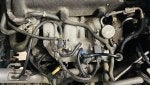
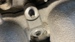
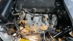
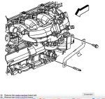
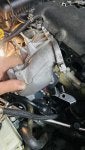
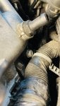
Hi group. Has anyone done a replacement of crankshaft sensor in their solstice Gxp 2.0 litre? I have a code po 335 and one solution is to change the sensor. Is there a technique that someone can share with me, I do have a hoist so wondering if it’s easier to do from underneath as the sensor is just above starter? Rick

Replacing crankshaft sensor
1 reading
Rixfix

") It's past five on a Friday night!
It's past five on a Friday night!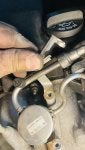


-
?
-
?
-
?
-
?
-
?
-
?
-
?
-
?
-
?
-
?
-
?
-
?
-
?
-
?
-
?
-
?
-
?
-
?
-
?
-
?